The surface roughness symbol can be placed on the extension line of the component as shown in Fig. The root symbol is placed on a drawing with the tip of the triangle in contact with the surface including on vertical faces it has to be rotated to the left then.
Surface Roughness Indication Symbols Surface Roughness Symbol Indication In Hindi Youtube
The root symbol can also be placed on a dimension lead line as long as it stays readable.
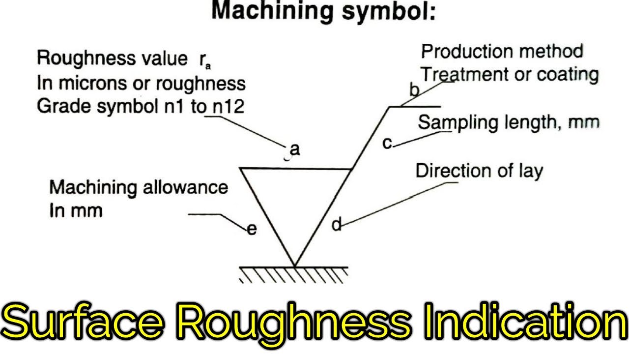
. Its value is shown in position a of the surface texture symbol in Fig. 43 Roughness Average Ra The principal parameter specified for roughness is the roughness average R defined in ASME B461. Are indicated around the surface symbol as shown in Fig.
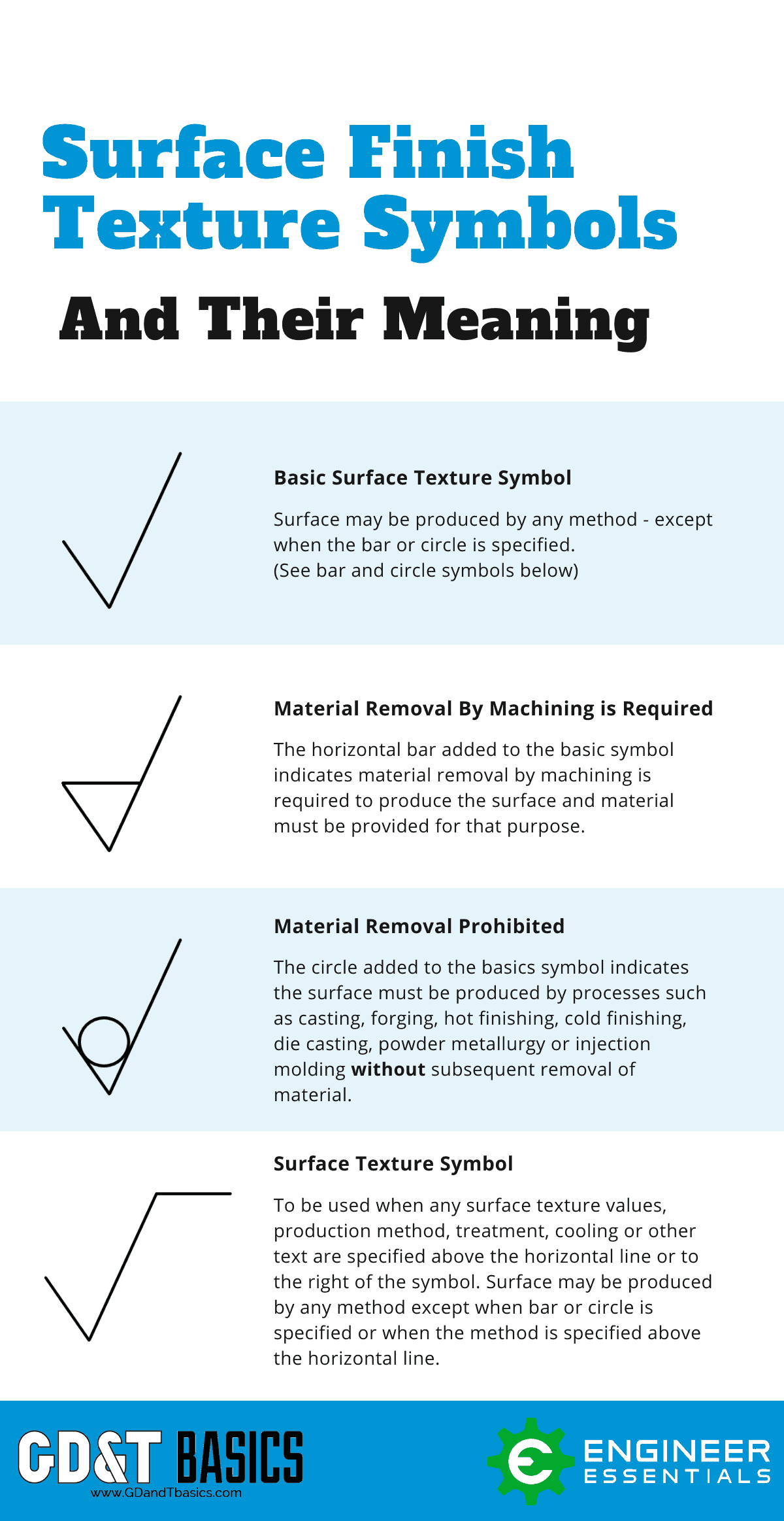
The quality of surface texture is indicated by certain symbols on technical drawings The basic symbol consists of two unequal legs at 600included angle to the line representing the surface under consideration with vertex touching as shown in figure. • Ra - Roughness average most commonly expressed in micrometers microns. Ra Rz in most cases.
This section will explain how to write these symbols to indicate surface textures. If your machine shop doesnt understand the symbol you should run away fast. Our chart of surface finishes by manufacturing process see above gives both.
Cylinder or Cylindrical DATUM. An italic f Latin small letter f written on a line representing a surface was an old way of indicating that the surface was to be machined rather than left in the as-cast or as-forged state. Surface finish Material.
Symbols that indicate the surface texture of machined and structural parts are used in industrial diagrams. The symbol is described in ASME Y1436M Surface texture symbols. You can find the list of common engineering drawing abbreviations.
For ISO and related drafting standards you can display surface finish symbols per 2002 standards by selecting Display symbols per 2002 in Document Properties Surface Finishes. Agiecharmilles edm surface finish cross reference chart agie charmilles edm finish scale ra micro meter ra micro inches rms 2 08 3 14 3 90 the principal iso standard that specifies syrface roughness is iso 1302 and defines the surface roughness symbology and additional requirements for engineering drawings the details in iso surface finish. When no value is shown use 03 inch 08 millimeters.
Roughness symbol on drawing. Surface Finish consists of waviness lay and roughness but it is common for only roughness to be specified on technical drawings. Surface roughness is indicated in the form of symbols on an engineering drawing.
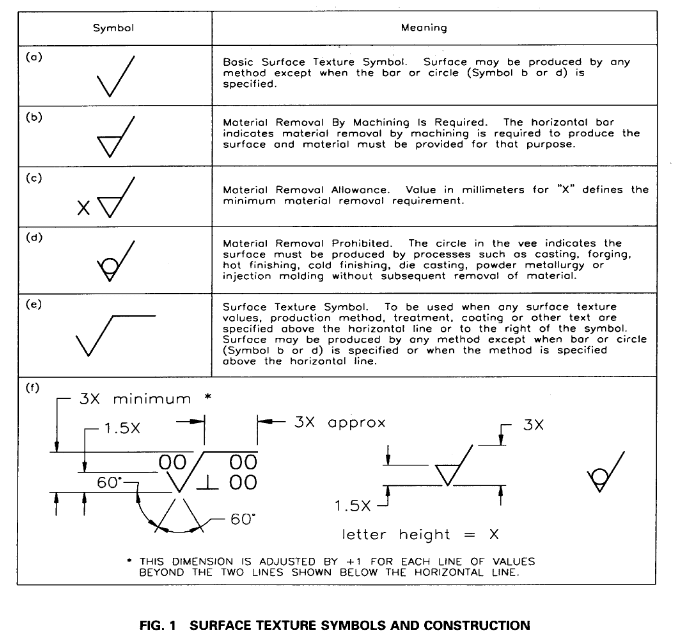
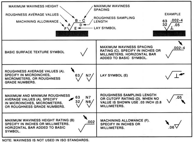
Example 63 32 002-4 05 002-4 05 06 60 63 002 lay symbol e roughness sampling length or cutoff rating d. This basic open tick Figure 613a has no significance of its own. Countersink Head CBORE or CBORE.
Closing the tick symbol Figure 613b indicates that the surface must be machined. 3b according to ISO 32741975 7. Roughness value in micrometers preceded by parameter symbol.
The surface roughness is generally indicated with the symbol and displays information including surface roughness value cutoff value machining method sampling length surface waviness and crease direction symbol as below. Ra and D are two important surface finish parameters The Surface Finish Units we would use for parameters like Ra would be either micro-inches English or Imperial or micrometers Metric. Horizontal bar added to basic symbol.
Ra Rz in most cases. Surface finish symbols are formed by combining the Symbol and Lay Direction direction of lay. Ra is average roughness and it under-estimates surface height variations.
This basic symbol consists of two legs of unequal length. How do you show surface roughness in drawing. ASME Y1436M - Surface Texture Symbols These are used on manufacturing drawings that specify surface finish in terms of an ISO standard.
3 SYMBOLS USED FOR INDICATION OF SURFACE TEXTURE 31 The basic symbol consists of two legs of unequal length inclined at approximately 60 to the line representing the considered surface as shown in figure 1. Ra is average roughness and its under-estimates surface height variations. Specify in inches or millimeters.
The basic tick comprises two lines at 60 to each other. Degree of angle DIA. Our chart of surface finishes by manufacturing process see above gives both.
Position on a drawing. The basic symbol consists of two legs of unequal lengths making an angle of about 60 between the legs. Rz is mean roughness depth and it approximates the size of the most severe surface height variations.
ISO Surface Parameter Symbols Rp max height profile Rv max profile valley depth Rz max height of the profile Rc mean height of profile Rt total height of the profile Ra arithmetic mean deviation of the profile Rq root mean square deviation of the profile Rsk skewness of the profile Rku kurtosis of the profile. A surface roughness value cut-off value or reference length processing method grain direction surface undulation etc. Maximum waviness spacing roughness sampling length e lay symbol maximum waviness spacing rating c.
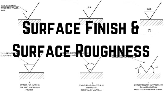
The surface finish symbols used in engineering drawings are defined by technical standards such as ISO ANSI or AS Australian standard. The quality of a surface finish on a metal surface produced by production method other than machining is shown on the drawing by a tick symbol as shown in fig-A. Understanding surface roughness symbols.
Shaped Surface The trace left by a cutting instrument is parallel to the projection plane in the drawing. The pictorial representation using these symbols is defined in ISO 13022002. These are inclined at approximately 60 degrees to the line representing the surface to be machined with the vertex touching it.
The f came from finish in the sense of machine finish as opposed to raw stockcastingforging. Ra and D are two important surface finish parameters The Surface Finish Units we would use for parameters like Ra would be either micro-inches English or Imperial or micrometers Metric. When we try to measure a surface finish the methods fall into three categories.
Surface Finish consists of waviness lay and roughness but it is common for only roughness to be specified on technical drawings. This symbol alone has no. Rz is mean roughness depth and it approximates the size of the most severe surface height variations.
When we try to measure a surface finish the methods fall into three categories. 2 hours agoWhere as in turbulent flowR4000 the friction factor depends upon the Reynolds numberR and on the relative roughness of the pipe 𝜀 Where𝜀 is the average tment of turbulent pipe flow in appearance of surface roughness is wall deposit. Each roughness grade number can be correlated to a specific Ra number that is expressed in microns.
You can select the face in a part assembly or drawing document. Other options are available and in particular simplified writing. There are three surface roughness symbols see figure below indicating the surface a required material removal b.
The symbols are as follows. The tick symbol is placed on the surface or an extension drawn to it.
Surface Roughness Symbol In Drawings Mechanical Engineering General Discussion Eng Tips
Complete Surface Finish Chart Symbols Roughness Conversion Tables
Dimensions Surface Finish Roy Mech

Solved Iso Surface Roughness Symbol Missing Roughness Autodesk Community

Surface Finish Wikipedia
Surface Finish Surface Roughness It S Indications Symbols
The Basics Of Surface Finish Gd T Basics
Iso Surface Roughness Symbols Terminology
0 comments
Post a Comment